Tuesday, May 3, 2016

Final Project - Smart Water Filter

1. Project information :


Complete project details can be found from the below given links


2.Poster session information:


Poster presentation of the project:


Poster Presentation for smart water filter

Results:

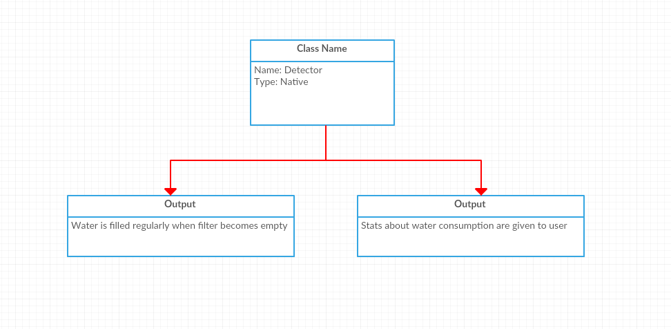
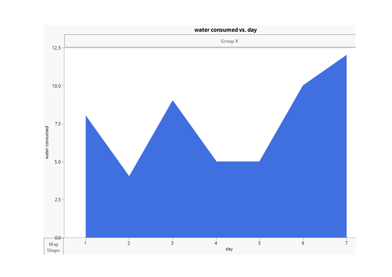
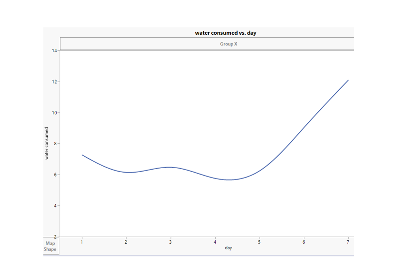
Data collected about water usage is taken by arduino and analysis is done on day wise water consumption from the site of water filter. These results are shown in form of graph to users. These reports are sent in form of email to users. Users will get to know about how much water they are taking now and how they can plan to change their daily schedule to consume more water if they are consuming less water. Graphs help sers to understand easily about the data.

Graph-1


Graph-2


Graph-3

Graph-4
Results of temperature and humidity values which are collected to calculate average


Temperature and Humidity values

3.Demonstration:


Smart water filter system functionality is demonstrated in the below video. I have explained how the entire system functions and how the internal operations takes place. I have used two different filters one which is empty and the other which is full for the demonstration. When water level changes signal is sent from arduino to relay which is operates the water valve. When the light blinks on relay it indicates that state of water valve is changed.


4.Link to Software:


Software used for my project:

http://blog.initialstate.com/category/arduino-2/
http://www.jmp.com/en_us/home.html


General Software useful for IOT:

Operating Systems:

https://www.mbed.com/en/
http://developer.ubuntu.com/en/snappy/
http://www.contiki-os.org/
http://raspbian.org/
http://www.riot-os.org/
http://spark.github.io/
http://webinos.org/

APIs

https://bip.io/
http://www.zettajs.org/
http://wiki.1248.io/doku.php

Platforms for IOT projects:

http://iot-dsa.org/
http://www.m2mlabs.com/
http://bsautner.github.io/com.nimbits/
http://osiot.org/
https://prplfoundation.org/
https://www.rabbitmq.com/
http://www.sitewhere.org/
http://webinos.org/
https://yaler.net/download
https://github.com/Picolab/

Protocols:

https://www.amqp.org/
http://coap.technology/
http://xmpp.org/about/history.html
https://www.oasis-open.org/news/pr/oasis-members-to-advance-mqtt-standard-for-m2m-iot-reliable-messaging
http://www.vscp.org/

Middleware:

http://www.openremote.org/display/HOME/OpenRemote
https://code.google.com/archive/p/iotsys/
http://www.kaaproject.org/

Node Flow Editors:

http://nodered.org/
http://thethingbox.io/

Toolkits:

https://github.com/kinoma
http://iot-toolkit.com/

Data Visualization:

https://thingspeak.com/
https://github.com/Freeboard/freeboard

Hardware:

http://www.arduino.cc/en/Main/ArduinoEthernetShield
http://beagleboard.org/getting-started/
http://www.arduino.cc/en/ArduinoCertified/IntelGalileo
https://pinocc.io/
http://we-io.net/hardware/
http://wizwiki.net/wiki/doku.php

Home Automation:

http://www.homegatewayinitiative.org/
https://developers.ninja/
http://www.openhab.org/
http://www.eclipse.org/smarthome/
http://projects.privateeyepi.com/
http://razberry.z-wave.me/
http://thethingsystem.com/index.html

Other useful links:

http://www.osrfoundation.org/
https://opengarden.com/
https://openwsn.atlassian.net/wiki/
https://www.cooking-hacks.com/documentation/tutorials/ehealth-v1-biometric-sensor-platform-arduino-raspberry-pi-medical
http://www.takingspace.org/
http://flood.network/
http://thingful.net/
http://www.ehcache.org/
http://hazelcast.org/
https://allseenalliance.org/
http://openconnectivity.org/
http://www.compose-project.eu/
http://www.eclipse.org/
http://www.oshwa.org/


5.Project sites I used in creating the project:


http://www.bc-robotics.com/tutorials/controlling-a-solenoid-valve-with-arduino/
http://makezine.com/projects/wifi-water-valve/
http://www.14core.com/wiring-esp8266-nodemcu-with-hcsr04-ultrasonic-sensor/
http://tech.jolowe.se/arduino-with-relay-module/
https://learn.adafruit.com/dht-humidity-sensing-on-raspberry-pi-with-gdocs-logging/overview
https://microsoft.hackster.io/en-US
https://www.hackster.io/raspberry-pi/products/raspberry-pi-2-model-b
https://www.raspberrypi.org/blog/getting-started-with-iot/
https://www.openhomeautomation.net/internet-of-things-project-raspberry-pi-2/
http://www.instructables.com/id/Intel/
https://software.intel.com/en-us/iot/about/projects
https://www.hackster.io/intel/products/intel-edison
http://www.generationrobots.com/blog/en/2015/02/5-project-ideas-intel-edison-board/
http://nevonprojects.com/iot-projects/
https://www.quora.com/What-are-some-cool-IoT-ideas-and-projects
http://www.informationweek.com/software/enterprise-applications/10-raspberry-pi-projects-for-learning-iot/d/d-id/1320757?image_number=2
http://www.cisco.com/c/en/us/solutions/internet-of-things/overview.html
https://www.udemy.com/introduction-to-iot-using-raspberry-pi-2/


6.Next Steps for Smart Water Filter:


6.1. Implementing water quality assurance system. Adding water quality sensor and continuously monitor the quality of water. If the water quality is not good immediately message and email will be sent to users. This can alert users to take care by not drinking the low quality water.


Water Quality Sensor


6.2 Send maintenance alerts to the users in regular time intervals. As smart water filter system is related to people's health it should have clean environment. Sending emails and messages and reminding people about service will help users to maintain a clean water system. 


Email reminders

6.3 Maintain a stable water level based on the usage. Monitor the water level continuously and predict the required water level at different time intervals of day. measure the required water level and maintain this level as predicted. This gives out fresher water in every consumption. This reduces water remaining stagnant for a longer time.

6.4 In this water filter we can know the total usage of the family but we will not know how much water each individual is using. To solve this problem we can use fingerprint scanner at the tip of water filter. It will first register all the family members who are users of smart water filter. Whenever users consume water it will record who is drinking the water. By following this system we can accurately measure the individual water consumption.


Filter switch for water flow


Fingerprint Scanner


Monday, April 25, 2016

parts of your project report

Service Specification:


1 Service One-Line Description
The Smart water filter manages water level automatically in the filter.

2 Service Abstract
The takes care of water level in the filter. It monitors the water level continuously and refills when water water level gets low. Temperature and humidity are measured and every hour and average values are calculated per day. Average water which is to be consumed is compared against water which is consumed now. Total water consumption is measured and average water consumption per person is calculated and these stats are sent to users.

3 Service Context
The usage context for the Smart water filter is shown in below figure. The service is intended to be used by any house, school, college, office or public place. It also provides stats about water consumption by the family members.


Services in smart water filter


4 Intended Utilization Scenarios
The intended utilization scenario is water filter management without manual intervention by a family. In this scenario, water filter will be used by all the family members and they need not to manually fill the filter every time. Whenever the water level in filter gets low water valve turns on and then water will be refilled automatically. Family receives stats about water consumption.


Functional View Specification: 


1 Goals
The overall goal of this project is threefold:
• Reduce manual intervention in water filling system for filter
• Provide a perfect water management system for filter
• Provide stats about water consumption for users

2 Audience
The target user for this site will be for all age groups. Its is useful for everyone who wants a smart water filter. Target site users will enjoy the comfort of getting free from continuous monitoring of water level.

3 Project Phases 

This project is divided into two phases:

In Phase 1: created a site map, strategic brief and this specification, as well as hosting hardware specifications and creating the visual design for the site.

Phase 2:  will introduce interactive tools that individuals can maintain. Prepare system to report users about water consumption.

Tools:

Email
The smart water filter will also implement an opt-in email system. Family members will be able to subscribe to receive stats about water consumption for the current temperature and humidity

Hardware and Hosting

Hosting specifications and configuration

Arduino
Raspberry pi
ultrasonic sensor
DHT11
water valve
9v battery
connecting wires
water filter

Operational View Specification:


In operational view specification, various options pertaining to IOT system deployment and operation are defined, such as, service hosting options, storage options, device options, application hosting options, etc.

Functional groups to operational view specifications for the smart water filter can be mapped to IOT system as follows;
Devices: Computing Device (ESP8266 Node MCU WiFi Module), Raspberry Pi, Ultrasonic Sensor(to measure water level), Relay, water valve, DHT11
Communication APIs: Internet (HTTP and REST APIs).
Communication Protocols: link layer - 802.11, network layer - IPv4/IPv6, transport layer - TCP, and application layer - HTTP.
Services:
Controller Service: Arduio IDE, implemented in c, and runs as a native service.

Database: Google SpreadSheet

Management:
Application Management: automatic
Database Management: Google Spreadsheet database management.
Device Management: Arduino - ESP8266 Node MCU WiFi Module device management. 

the operational view of Smart water filter looks as below:


Operations Overview

above picture gives the flow from start to end. explains how each and every operation in the project is done.


Device and Component Integration:


In Device and Component Integration design methodology describes the integration of the devices and components. In this smart water filter IOT project the devices and components used are, Arduino ESP8266 Node MCU WiFi module, Ultrasonic sensor, DHT11, water valve and relay.

Integration of Node MCU and Ultrasonic Sensor, water valve, relay and battery:


Circuit Diagram


All the devices are connected as shown in the above diagram. As arduino has maximum of 5v we are using relay to operate water valve. Relat takes 5v signal from arduino and operated the water valve with help of external power supplying agent.

DHT11 integration for reading temperature and humidity:


DHT11 setup


Smart Water Filter setup


References:
http://searchsoftwarequality.techtarget.com/definition/functional-specification
http://www.bc-robotics.com/tutorials/controlling-a-solenoid-valve-with-arduino/
http://tech.jolowe.se/arduino-with-relay-module/
http://ptgmedia.pearsoncmg.com/images/9780321802057/downloads/ServiceSpecificationExample.pdf
http://ioeverything.blogspot.com/
http://programmers.stackexchange.com/questions/209234/what-are-the-differences-between-functional-operational-and-technical-requireme

Monday, April 18, 2016

Fundemental parts of project

Smart Water Filter:

0.1 Introduction:

Purpose:


The purpose of this document is to present a detailed explanation of Smart Water FIlter. This will describe us  purpose and features of the system, the interface of the system, what the system will do, the constraints under which it must operate and how the system will react to external stimuli. This document is intended for both the stakeholders and developers of  system.

1.0 Purpose & Requirements Specification

1.1 Purpose of Project:


Over the past few years, the definition of “Smart Home” has evolved to mean many things to many people. Yet, one thing remains constant: part of being “smart” is utilizing information and communications technology (ICT) and the Internet to address urban challenges. My project is related to Home Automation in IoT.

Home automation: This is where a home’s electrical devices are connected to a central system that automates those devices based on user input. For example, you push a button and your shades go up, or you give a voice command and your lights turn on.

Connected devices: These are electrical devices that are intelligent, courtesy of a connection to the Internet and sensors. These devices know or are able to anticipate what a user needs. At first, this intelligence comes from user programming, but with time the device can learn and adapt to patterns and interact with its users.

Internet of Things: IoT is the magic dust that turns the automated home into the smart home. With a combination of sensors, smarts and systems, IoT connects everyday objects to a network, enabling those objects to complete tasks and communicate with each other, with no user input.

Smart Water Filter is a prat of smart home project which belong to Home Automation in IoT.


1.2 Behavior :


Water filter will be monitored continuously and it is refilled automatically without any manual intervention. Water consumption stats are collected and minimum amount of water which is to be consumed based on the weather conditions is measured and sent to the users. This can be used at home, office,schools, college or any public places.


1.3 System Management Requirement:


This system provides remote monitoring  and control function. Administrator will be appointed based of the size of institution, who monitors sensors, water management issues, timing issues (delay in water supply). He also monitors the quality of water and manage stats about water consumption.


1.4 System Hardware Requirements:


Equipment Required:
Raspberry Pi
Ultrasonic Sensor
DHT11
Water valve
Pipe for water
water filter


1.5 Data Analysis Requirement:


System will maintain a repository to provide information about water consumption. System will also calculate the average water consumption by users and compare with the required water level consumed by normal person based on the weather conditions and should report it to user.


1.6 Application Deployment Requirement:


Smart Water Filters can be installed in any place. To install Smart Water Filter System in any institution will happen at once which may take few hours of shutdown of water supply for few hours. Internet connection is mandatory for these devices which can be provided with WiFi or Ethernet. These devices fetches and update the information from/in to a database, which is located on a web-server. User should be connected with internet to get the updates on water consumption statistics.


2.0 Process Specification:

2.1  Use case diagrams:


2.2 Sensor level diagram :


Ultrasonic sensor continuously monitors water level in filter . If it finds that water level is minimum then it turns on water valve until filter is full an then turns off water valve it will update those details in Database. It does this process continuously.It updates water consumption levels to database.


2.3 Process Diagram:


3.0 Domain Model Specification:


4.0 IOT level Specification Model:


Smart water filter belongs to IOT Level-1 specification because it uses a single level node/sensor for collecting data and store it in local database. It also uses local analysis , Rest services. Project related diagrams which describes the elements relationships are provided below.

5.0 Information Model Specification:


6.0 Service Specification Model:


References:
  • http://www.networkworld.com/article/2874914/internet-of-things/what-is-home-automation-and-how-do-i-get-started.html
  • https://creately.com/app/?tempID=gc7qvpsj1&login_type=demo#
  • http://ioeverything.blogspot.com/

Sunday, March 20, 2016

Project Proposal - Smart Water Filter

Water filer of small capacity get emptied very frequently. We forget to fill them in advance in order to use water when needed. To solve this problem I am doing smart water filter which takes care of water level in filter and refills it every time water level is low. I am planning to use ultrasonic sensor to measure existing water level in filter. If this is not giving efficient details I am planning to use IR proximity sensor. I will take data of how much water is consumed per day by all the family members. I will send weekly reports of statistics of water consumption. Based on the weather conditions I will give min amount of water consumption for a family based on its size. This can be done by this project.  It will auto fill water filter without manual intervention. Will send statistics about water consumption of family based on weather conditions.

Things : Ultrasonic sensor or IR distance sensor, DHT11

Data : amount of water consumed, temperature and humidity

Process : when the water filter becomes empty it automatically gets refilled. We need to keep on checking filter to refill it.

People : This projects manual intervention for refilling water filter. No manual effort is required. Data is collected about water consumption and people in the family will get to know how much water they are consuming daily. How much should they consume as per the weather conditions.


Tuesday, February 23, 2016

Smart Traffic Signals

MQTT Class effort

a. What I have done in the class:
I have integrated my Raspberry Pi and Arduino through MQTT, to listen and respond on photocell(sensors that allow you to detect light) readings. I used pubsubclient to test request-response on wifi. Arduino - Pubsubclient provides examples of basic tests, so that we can test pre requirements. I was the first person to complete the class task and helped others in doing the same.

Arduino - Hardware
Arduino WiFi Module
Photocell
Resistors (10k, 330 ohm)
LED
Jumping wires
Arduino - Software / MQTT
There are four main tasks the Arduino software needs to take care of for this example:
Gather light sensor readings periodically
Publish sensor readings via MQTT
Listen for commands via MQTT
Control the LED based on a setpoint
An MQTT client is created in the setup function.

Experiment overview:

The MQTT client connects (if it is not already connected).

Based on the “sensing mode” the application decides how to drive the LED.  It could be OFF, ON or SENSE.  In the SENSE case a light reading is taken and the LED is driven according to a hardcoded setpoint.

I was able to operate 3 different LED lights using mobile app with help of MQTT protocol.Below is the video which shows demonstration of the work.

Video:


Connections:


Code:


#include <ESP8266WiFi.h>
#include <PubSubClient.h>
#include <String.h>

// Update these with values suitable for your network.

const char* ssid = "Pi_AP";
const char* password = "Raspberry";
//const char* mqtt_server = "broker.mqtt-dashboard.com";
const char* mqtt_server = "192.168.0.34";

WiFiClient espClient;
PubSubClient client(espClient);
long lastMsg = 0;
char msg[50];
int value = 0;
int timer = 200;
int ar[] = {15, 12, 4, 16}; 


void setup_wifi() {

  delay(10);
  // We start by connecting to a WiFi network
  Serial.println();
  Serial.print("Connecting to ");
  Serial.println(ssid);

  WiFi.begin(ssid, password);

  while (WiFi.status() != WL_CONNECTED) {
    delay(500);
    Serial.print(".");
  }

  Serial.println("");
  Serial.println("WiFi connected");
  Serial.println("IP address: ");
  Serial.println(WiFi.localIP());
}


void off() {

  for(int i = 0; i < 4 ; i++){
  digitalWrite(ar[i], LOW);
  }
  
}


void go() {
  off();
  digitalWrite(15, HIGH);
}

void stops() {
  off();
  digitalWrite(12, HIGH);
}

void yeild() {
  off();
  digitalWrite(4, HIGH);
}


void callback(char* topic, byte* payload, unsigned int length) {
  Serial.print("Message arrived [");
  Serial.print(topic);
  Serial.print("] ");
  
  Serial.println();

  String s = "";

  for(int i = 0; i< length; i++) {
    char a = ((char)payload[i]);
    s = s + a;
  }

  if( s == "off") {
    off();
  }
  else if(s == "stop") {
    stops();
  }
  else if(s == "go") { 
    go();
  }
  else if(s == "yeild") { 
    yeild();
  }
  
}

void reconnect() {
  // Loop until we're reconnected
  while (!client.connected()) {
    Serial.print("Attempting MQTT connection...");
    // Attempt to connect
    if (client.connect("ESP8266Client")) {
      Serial.println("connected");
      // Once connected, publish an announcement...
      client.publish("outTopic", "hello world");
      // ... and resubscribe
      client.subscribe("inTopic");
    } else {
      Serial.print("failed, rc=");
      Serial.print(client.state());
      Serial.println(" try again in 5 seconds");
      // Wait 5 seconds before retrying
      delay(5000);
    }
  }
}

void setup() {
  //pinMode(12, OUTPUT);     // Initialize the BUILTIN_LED pin as an output

  for(int i = 0; i < 4; i++){
    pinMode(ar[i],OUTPUT);     
  }
  Serial.begin(115200);

  setup_wifi();
  client.setServer(mqtt_server, 1883);
  client.setCallback(callback);
}

void loop() {

  if (!client.connected()) {
    reconnect();
  }
  client.loop();

  long now = millis();
  if (now - lastMsg > 1000) {
    lastMsg = now;
    ++value;
    snprintf (msg, 75, "hello world #%ld", value);
    Serial.print("Publish message: ");
    Serial.println(msg);
    client.publish("outTopic", msg);
    //callback();
  }

}


b. To whom I helped and What I did for them:

I was the first person to complete task of talking to MQTT server in class. I tried with example from arduino library and was able to communicate using MQTT. I explained this to entire class with help of professor. I told which program to use from code so that everyone can start MQTT communication from arduino.

I helped krishna, pavan and sandeep for executing the code for basic connection through MQTT.

c. Who helped me and What they did for me:
Pavan, Sandeep and Jorge helped to me find the coding and programing help from blogs which explains MQTT programing.


References:

  • http://www.rs-online.com/designspark/electronics/blog/building-distributed-node-red-applications-with-mqtt
  • http://jpmens.net/2013/09/01/installing-mosquitto-on-a-raspberry-pi/
  • http://pubsubclient.knolleary.net/
  • https://learn.adafruit.com/photocells/overview
  • http://m2mio.tumblr.com/post/30048662088/a-simple-example-arduino-mqtt-m2mio


Monday, February 15, 2016

Week-4-WIFI with Pi


WIFI AP using Raspberry Pi:

Current experiment is to create a Wi-Fi zone using Raspberry Pi. We will make use of Raspberry Pi and turn it into a router. We can connect to internet on other devices using new WIFI zone. I have done by following the below steps. This is a simple process to follow and in creating a customized WIFI. 

Initially I have updated the current version of packages using  sudo apt-get update

Now we need to install host access software into Pi. For this I have used "hostap" package in Raspberry Pi. 

sudo apt-get install hostapd isc-dhcp-server

Next step is setting DHCP server on Pi. For this we need to modify the existing files. Open the file dhcpd.conf

sudo nano /etc/dhcp/dhcpd.conf

We have 3 things to do here

1) Comment the below lines in file:

option domain-name "example.org";
option domain-name-servers ns1.example.org, ns2.example.org;

2) Uncomment the following line of code in file:

# If this DHCP server is the official DHCP server for the local
# network, the authoritative directive should be uncommented.
authoritative;

3) Add the following code at bottom of the page:

subnet 192.168.42.0 netmask 255.255.255.0 {
range 192.168.42.10 192.168.42.50;
option broadcast-address 192.168.42.255;
option routers 192.168.42.1;
default-lease-time 600;
max-lease-time 7200;
option domain-name "local";
option domain-name-servers 8.8.8.8, 8.8.4.4;
}


after completeing above 3 steps save the file and return.

Next open the file isc-dhcp-server

Find the following line in file INTERFACES=""  and update this to INTERFACES="wlan0" 

Save the file and return

Make sure that wlan0 is not active. Make it inactive using command  
sudo ifdown wlan0

Next we will set up the wlan0 connection to be static and incoming.
run sudo nano /etc/network/interfaces to edit the file

Find the line "auto wlan0" and comment it, if it is in the file. Comment each line after the current line also.

add the below lines into the file 

iface wlan0 inet static
  address 192.168.42.1
  netmask 255.255.255.0
  
Save the file and return.

Assign a static IP address to the wifi adapter by running 
sudo ifconfig wlan0 192.168.42.1

Now setting password for the network. For this we need to create a file and write into it. I am setting my password as Bhargav

create file using command 
sudo nano /etc/hostapd/hostapd.conf


Write the following code into file :

interface=wlan0
driver=rtl871xdrv
ssid=Pi_AP
hw_mode=g
channel=6
macaddr_acl=0
auth_algs=1
ignore_broadcast_ssid=0
wpa=2
wpa_passphrase=Bhargav
wpa_key_mgmt=WPA-PSK
wpa_pairwise=TKIP
rsn_pairwise=CCMP


save the file and return

Now we need to setup configuration file for Raspberry Pi. 
Run sudo nano /etc/default/hostapd

Find the line #DAEMON_CONF="" and edit it so it says DAEMON_CONF="/etc/hostapd/hostapd.conf"

Save the file and return


Configure Network Address Translation

This will allow multiple clients to connect to the WIFI network. Open the file "sysctl.conf" using the following command sudo nano /etc/sysctl.conf

At bottom of the file add line. This will start IP forwarding on boot up

net.ipv4.ip_forward=1


Save the file and return

sudo sh -c "echo 1 > /proc/sys/net/ipv4/ip_forward"

Run the following commands to create the network translation between the ethernet port eth0 and the wifi port wlan0

sudo iptables -t nat -A POSTROUTING -o eth0 -j MASQUERADE
sudo iptables -A FORWARD -i eth0 -o wlan0 -m state --state RELATED,ESTABLISHED -j ACCEPT
sudo iptables -A FORWARD -i wlan0 -o eth0 -j ACCEPT


Now changing the configuration so that WIFI connection is ready on startup. Run the following command 
sudo sh -c "iptables-save > /etc/iptables.ipv4.nat"

Open the file iptables.ipv4.nat using command  
sudo nano /etc/network/interfaces

add the below line at end of file 
up iptables-restore < /etc/iptables.ipv4.nat

Save the file and return


Updating the software so that the WIFI hardware is supported. Follow the below steps to setup software 

To download 

wget   http://adafruit-download.s3.amazonaws.com/adafruit_hostapd_14128.zip

To install 

unzip adafruit_hostapd_14128.zip
sudo mv /usr/sbin/hostapd /usr/sbin/hostapd.ORIG
sudo mv hostapd /usr/sbin

Give permission for execution

sudo chmod 755 /usr/sbin/hostapd

WIFI zone on every restart

Now we are all set to set our own WIFI using Raspberry Pi. This can be hosted using following command 

 sudo /usr/sbin/hostapd /etc/hostapd/hostapd.conf

 This displays the name of your WIFI on other devises. You can select the newly created WIFI and connect to it using the password. 

 Here are the images of my WIFI zone.

 This images shows the list of available WIFI networks. "BHARGAV-AP" is my WIFI. 


 This image shows that I have conected to my WIFI on my mobile.


 This image is to show that Arduino client is able to access the WIFI created using Raspberry Pi. This is showing the available WIFI which could be accessible.


 This images shows that Arduino client is able to connect to the newly created WIFI. 


Reference:
https://learn.adafruit.com/setting-up-a-raspberry-pi-as-a-wifi-access-point/install-software